Incident Report — OTGW WiFi and ATAG A244EC non responsive

This Forum is about the Opentherm gateway (OTGW) from Schelte

Moderator: hvxl

Post Reply
Aboreon
Starting Member
Starting Member
Posts: 3
Joined: Wed Jul 16, 2025 8:28 pm

Incident Report — OTGW WiFi and ATAG A244EC non responsive

Post by Aboreon »

Hardware and Firmware Details
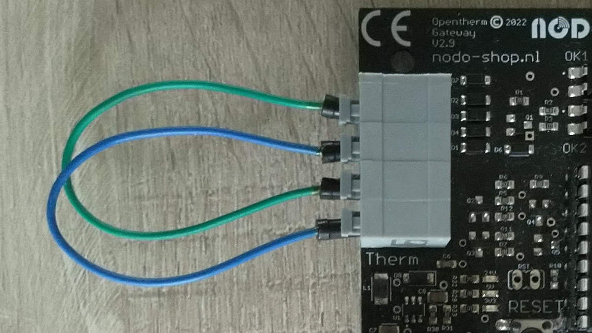
  • OTGW Model: WiFi version purchased from Nodo-shop
  • OTGW Developer: Robert van den Breemen
  • OTGW Firmware Version: 0.10.2+50c3ed2
  • Firmware Compilation Date: Mar 14, 2023 23:02:12
  • PIC Firmware: Available, Version 2.1 (Device: pic16f1847, Type: diagnose)
  • Arduino Core: 2_7_4 (Espressif SDK: 2.2.2-dev)
  • CPU Speed: 160 MHz
  • Flash Chip: 4 MB (LittleFS: 1 MB)
  • MAC Address: F4:CF:A2:FA:1A:5A
  • IP Address: 192.168.50.22
  • Heap Mem (Free/Max): 14584 / 13232 bytes
  • Sketch Size (Used/Free): 597664 / 1499136 bytes
  • WiFi Network: TSEO (Signal: -65 dBm, Quality: 80% - Amazing)
  • MQTT Connected: Yes
  • HA Integration: True
  • Thermostat Connected: False (this goes to true when the gateway firmware is active
  • Boiler Connected: False
  • Uptime: 00:22 (h:m)
  • Reboots: 26
  • Last Reset Reason: External System

Setup Goals
  • Final Goal: Inventum EVA thermostat → OTGW → Inventum Spaarpomp → ATAG A244EC
  • Current Test Setup: Tado thermostat → OTGW → ATAG A244EC
Just Tado smart thermostat + ATAG A244EC
This works well, I can start and stop the heating by increasing and lowering the temp on the thermostat

Problem Description with opentherm gateway
When using the normal gateway firmware it seems to register the thermostat and gives responses like which to my understanding are correct. Thermostat put messages in the log and on MQTT

Code: Select all

20:23:59.497289	T00390000	Read-Data 	Max CH water setpoint: 0.00
20:24:00.001877	T00390000	Read-Data 	Max CH water setpoint: 0.00

20:43:40.497470	T00240000	Read-Data 	Electrical current through burner flame: 0.00
20:43:40.998797	T00240000	Read-Data 	Electrical current through burner flame: 0.00

20:43:36.999114	T007B0000	Read-Data 	DHW burner operation hours: 0

20:44:43.976385	T80394600	Read-Data 	Max CH water setpoint: 70.00
20:44:44.458994	T80394600	Read-Data 	Max CH water setpoint: 70.00
No boiler messages, if I just swap out the OTGW and connect the thermostat directly this works fine but when adding the OTGW it goes to error C61
From the manual ATAG manual: "C 61 geen communicatie via Z-bus (reset alleen mogelijk door spanningsonderbreking)"
Which means no communication via Z-Bus reset only possible via power interrupt

When I try to do this it go to "normal" operating status but still no response or data from the boiler in the OTtools


OTGW Diagnostics (via https://otgw.tclcode.com/diagnose.html)

Test 1 (LED test):
looks good

Test 2 (Pulse timing):

Code: Select all

90181700  Write-Data  Room temperature: 23.00
505,512,496,1004,495,504,996,1003,496,496,503,504,496,503,496,504,495,504,496,503,996,502,497,1003,496,504,495,504,495,504,496,504,495,504,995,1004,995,503,496,503,496,1004,495,504,495,504,496,504,495,504,495,504,496,504,495,504,995.
Test 3: Bit timing boiler
No output

Test #4: Delay symmetry
Error: Interfaces don't appear to be looped

Test #5: Voltage levels

Code: Select all

Power supply: 3.339 V
Reference: 1.222 V
Thermostat: 0.896 / 1.998 V
Boiler: 0.000 V
Reference voltage setting (0..9): [default]
Test #6: Idle times

Code: Select all

T: 467.114
T: 466.945
T: 466.925


Now what I do not understand or know how to troubleshoot further is why the boiler does not seem to be able to do anything.

Hopefully anyone here has any ideas or tips for me. thanks!
hvxl
Senior Member
Senior Member
Posts: 2035
Joined: Sat Jun 05, 2010 11:59 am
Contact:

Re: Incident Report — OTGW WiFi and ATAG A244EC non responsive

Post by hvxl »

Aboreon wrote: Wed Jul 16, 2025 9:20 pm Test #4: Delay symmetry
Error: Interfaces don't appear to be looped
This indicates a hardware fault of the OTGW or a bad connection, assuming you followed the test instructions and looped the OTGW thermostat terminals to the boiler terminals as shown in the picture below.

Image

Make sure you properly soldered the connector onto the PCB.
Schelte
Aboreon
Starting Member
Starting Member
Posts: 3
Joined: Wed Jul 16, 2025 8:28 pm

Re: Incident Report — OTGW WiFi and ATAG A244EC non responsive

Post by Aboreon »

Hallo Schelte,

Thanks for the response I did not do the looping. However now I did and it still gives the same problem.
I let Nodo solder and flash the otgw.
WhatsApp Image 2025-07-17 at 18.50.30.jpeg
WhatsApp Image 2025-07-17 at 18.50.30.jpeg (100.3 KiB) Viewed 455 times
result still

Code: Select all

Enter test number: 4
### Error: Interfaces don't appear to be looped
which I gues means I need to contact nodo or any other tips i can try?
hvxl
Senior Member
Senior Member
Posts: 2035
Joined: Sat Jun 05, 2010 11:59 am
Contact:

Re: Incident Report — OTGW WiFi and ATAG A244EC non responsive

Post by hvxl »

That is strange. The Nodo shop fully tests a board before shipping when you buy the solder service. Have you connected something other than an Opentherm connection to the board at some point that may have damaged some components?

Do you have a multimeter? If so, please measure the voltage on the boiler pins of the connector on the bottom of the board with the OTGW powered and the loops in place. There should be some noticeable voltage there. Somewhere in the range of 5V to 20V. If not, there is a bad connection between the wires and the connector. If you do see the voltage, you can try to swap the wires on one side to reverse the polarity. That will direct the current through two different diodes. I'm not sure if the Nodo shop tests both polarities.

If the problem persists and you are up for it, we can investigate further step by step to determine what is broken. But given that you bought the solder service, I guess you would probably prefer to send the board back for investigation.
Schelte
Aboreon
Starting Member
Starting Member
Posts: 3
Joined: Wed Jul 16, 2025 8:28 pm

Re: Incident Report — OTGW WiFi and ATAG A244EC non responsive

Post by Aboreon »

Hello Schelte,

Managed to borrow a multimeter. Hope im doing this right, see screen
otgw multimeter
otgw multimeter
Untitled.jpg (119.6 KiB) Viewed 151 times
it seems like it registers 1.5 volts which is far from the 5v to 20v you mentioned.

To your question:
Have you connected something other than an Opentherm connection to the board at some point that may have damaged some components? maybe
- I have had on-off from my atag boiler connected before the opentherm. (was at that moment not aware that I needed to switch the connector in the CV)
- I have a hybrid system with an inventum heatpump this has a poweradaptor in between the heatpump and the thermostat which has an external powersource When I measure this output it gives 22.7v towards the thermostat and about 6.6 towards the heatpump. (I have had it connected on both sides I think when trying. Aftwards I switched to my tado thermostat to get it working first with just a thermostat and CV and leave the heatpump out of it.

let me know what you think, thanks for the support!
hvxl
Senior Member
Senior Member
Posts: 2035
Joined: Sat Jun 05, 2010 11:59 am
Contact:

Re: Incident Report — OTGW WiFi and ATAG A244EC non responsive

Post by hvxl »

You measure correctly, as far as I can tell. But the result is not correct. I checked with one of my own OTGW's and I get 16.9V.

I do not expect connecting the on/off input of a boiler to the OTGW to cause any damage. Such an input doesn't normally provide a lot of current as it is designed to be short-circuited. However, a power injector intended to supply power to a thermostat is likely to be able to supply a fair bit of current. At 22.7V that may very well have blown out a zener diode. Most likely D10.

A blown zener will usually present itself as a short-circuit. This results in the boiler interface being reduced to 2 diodes and an EB junction of a PNP transistor, essentially another diode. Each diode causes a voltage drop of around 0.6V. So three of them would result in about 1.8V. That's not too far off the 1.55V you measured, supporting the hypothesis that the zener is blown.

Considering that you had to borrow a multimeter, I think it's safe to assume you don't have the tools nor the desire to replace an SMD component yourself. I suggest you send the device back to the nodo-shop for investigation and repair.
Schelte
Post Reply

Return to “Opentherm Gateway Forum”